| Return
to main text |
Pinwheel Calculators
The operating heart of a pinwheel calculator is a cylinder
made up of a series of disks or wheels stacked side by side.
Every wheel has a setting lever and a series of nine pins, each
of which can be made to protrude or retract according to the
position of the setting lever.
 In the illustration, the
setting lever is set to five and five pins protrude from the
surface of the cylinder. When the whole cylinder is rotated, the
protruding pins mesh in turn with a transfer gear which advances
the output register by five divisions.
In the illustration, the
setting lever is set to five and five pins protrude from the
surface of the cylinder. When the whole cylinder is rotated, the
protruding pins mesh in turn with a transfer gear which advances
the output register by five divisions.
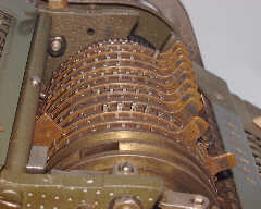 The pinwheel
cylinder of a Brunsviga calculator with 4 set in the ninth
position. Once set, the whole cylinder can be locked together and
rotated as a single unit.
The pinwheel
cylinder of a Brunsviga calculator with 4 set in the ninth
position. Once set, the whole cylinder can be locked together and
rotated as a single unit.
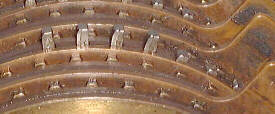 A close up of the four
protruding pins on the cylinder.
A close up of the four
protruding pins on the cylinder.
Simple addition
To perform a very simple calculation such as adding 3 to 5,
the action is as follows:-
- The output register (the row of figure wheels along the front
of the calculator) is set to zero.
- A pinwheel setting lever is moved down three clicks to set up
a three - three pins protrude from the cylinder.
- The crank handle is given one turn - the cylinder rotates and
the three protruding pins move the transfer gear on three
positions. This, in turn, moves the figure wheel so that it now
shows "3"
- A five is now set up on the pinwheel by moving the setting
lever a further two clicks.
- The crank handle is given another turn - the cylinder rotates
and now the five protruding pins move the transfer gear on a
further five positions. This leaves the figure wheel showing
"8"
This is the principle of operation. To perform a subtraction,
the handle is cranked in the opposite direction. Multiplication
or division is carried out by repeated addition or
subtraction.
The problem of the carry
For all but the most simple of calculations, it is necessary
to allow for a carry from one decade to the next. Unfortunately,
it is difficult to implement a carry on a mechanical
calculator.
Why?
The carry process requires input from two sources. A given
figure wheel has to decide:-
- Has the wheel to my right advanced beyond 9 and generated a
carry?
- How far is the transfer gear asking me to move forward?
Implementing this sort of thing in brass and iron would
quickly result in little heaps of gear teeth in the bottom of the
calculator and a jammed mechanism.
A problem is that the carry has to be added
sequentially from right (units) to left,
one digit at a time. This is because a carry
might in itself generate a further carry if added into a "9".
This implies that the arithmetic has to be carried out
sequentially, one digit at a time.
First, the units have to be added and any carry generated
added to the tens. Then the tens have to be added in on top of
the carry and any carry generated from this has to be added to
the hundreds and so on...
This can be done. All we need to start with is space on the
cylinder for the nine "units" pins, then we need a small gap.
Then we need space further round the cylinder for the nine
"hundreds" pins, then we need a small gap. Then we need ... hang
on, we've gone right round the cylinder. We need a bigger
cylinder.
In practice, this method would either require an unreasonably
large diameter cylinder or a calculator limited to three or four
digits.
Try something else
An alternative would be to arrange the pinwheels so that they
did not revolve as one unit. The first turn of the crank would
move the units pinwheel, advance the tens figure wheel and attend
to any carry. The second turn of the crank would then move the
tens pinwheel and so on. For a ten digit calculator made in this
way, the addition of two numbers would require twenty turns of
the crank. This seems excessive.
Is there a better way?
The method that is generally adopted is to separate the carry
procedure from the main process of arithmetic. This means that
the arithmetic can occur simultaneously on all columns of figures
and only a small diameter cylinder is required. (In practice, the
various pin arrays are staggered very slightly, just to avoid the
mechanical strains involved if many gear trains had to be started
simultaneously.) During the arithmetic process, any carries
necessary are "flagged". Once the arithmetic is complete, any
carries that have been flagged can be processed sequentially,
from right to left one digit at a time. Since the maximum
possible value for a carry is 1, a staggered array of individual
carry pins can also be accommodated on the small diameter
cylinder.
How is this achieved?
Each pinwheel has a carry pin permanently protruding from its
rear surface. This carry pin is mounted so that it can move
slightly sideways and it is spring loaded to one side. In its
normal position, as the pinwheel cylinder rotates, the carry pin
misses the transfer gear and has no effect. If, however, the
carry pin is made to move sideways, against its spring, it will
be able to mesh with the transfer gear and advance this by one
position.
So far so good. What is needed now is some means of setting
the carry pin into its active position when a carry is
required.
In order to do this, each transfer gear / figure wheel pair is
fitted with a carry warning cam, which can be set or cleared. In
the cleared position, the carry pin misses the cam as the
cylinder revolves and the cam has no effect. When it is in the
set position, the cam lies in the path of the carry pin and the
moving pin hits the surface of the cam. The carry pin is pushed
sideways by the cam so that it meshes with the transfer gear
whence further rotation of the cylinder advances the gear by one
position.
The carry cam becomes set when a figure wheel in the output
register revolves through nine to zero. It is cleared
automatically once the carry had been added.
Now we are nearly there, but there is still the problem of a
carry generating a further carry. (For the sake of the
description that follows, the far right pinwheel is called number
1, its neighbour to the left, number 2 and so on.)
The movable (arithmetic) pins lie in a narrow zone on the
front face of the pinwheel cylinder. As the cylinder is revolved,
the number set up on the individual pinwheels is transferred via
the transfer gears to the figure wheels of the output register.
If any figure wheel in the output register has revolved past 9,
then its carry warning cam is set.
The carry pins are arranged in a staggered array across the
rear face of the pinwheel cylinder, so that they come into
operation sequentially. The first to take effect is on pinwheel
2. Now, if the carry cam for figure wheel 1 is set, then the
carry pin on pinwheel 2 is pushed sideways, meshes with transfer
gear 2 and advances it and figure wheel 2. So the carry from
figure wheel 1 is added to figure wheel 2.
If figure wheel 2 has just moved from 9 to 0 then carry cam 2
becomes set.
As the crank handle continues to turn, the carry pin on
pinwheel 3 comes into position and in striking carry cam 2 gets
pushed sideways into transfer gear 3 etc, etc.
In this way, any required carries are passed along the output
register from right to left, one digit at a time.
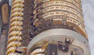
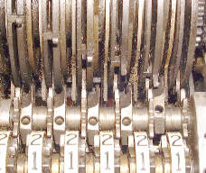 The
image shows the carry mechanism of the Marchant calculator. The
upper half shows the pinwheel cylinder with five staggered carry
pins descending diagonally from the top left. As the cylinder
rotates, the carry pins will move downwards. In the centre, just
above the figure wheels, there is the horizontal array of
transfer gears and carry cams. The rightmost carry cam has been
set and the corresponding carry pin is just about to engage with
the curved surface of the cam which will push it sideways to the
left so that it will engage with the transfer gear and increment
its figure wheel in the foreground.
The
image shows the carry mechanism of the Marchant calculator. The
upper half shows the pinwheel cylinder with five staggered carry
pins descending diagonally from the top left. As the cylinder
rotates, the carry pins will move downwards. In the centre, just
above the figure wheels, there is the horizontal array of
transfer gears and carry cams. The rightmost carry cam has been
set and the corresponding carry pin is just about to engage with
the curved surface of the cam which will push it sideways to the
left so that it will engage with the transfer gear and increment
its figure wheel in the foreground.
NOTE: The calculator is in the process of adding 1 to 9. The
rightmost (units) figure wheel has just advanced from 9 to 0. The
zero would show through a window in the front panel of the
calculator. As the pinwheel cylinder continues to rotate the
carry pin, in moving downwards, will advance the transfer gear
and the (tens) figure wheel, which would then show a 3 in the top
line and the 1 would move down to be visible in the display
window.
A variant - the Marchant calculator
 The Marchant
calculator is a variant on the pinwheel system. In this case the
cylinder is fitted with a gear segments whose 9 teeth all move as
a single unit. The position of the setting lever determines the
position at which the teeth retract into the cylinder. If, for
instance the setting lever is at position 2, then the gear
segment retracts suddenly after the transfer gear has been
advanced two positions and before it can be advanced further.
The Marchant
calculator is a variant on the pinwheel system. In this case the
cylinder is fitted with a gear segments whose 9 teeth all move as
a single unit. The position of the setting lever determines the
position at which the teeth retract into the cylinder. If, for
instance the setting lever is at position 2, then the gear
segment retracts suddenly after the transfer gear has been
advanced two positions and before it can be advanced further.
| Return to
main text | Go to Top |
29-Jan-2002
Images and Text Copyright © 2002 A.
Audsley, All Rights Reserved