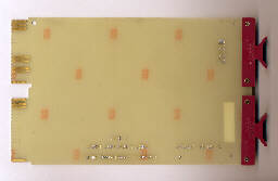
M9047 Grant Continuity Card
Enlarge
Unlike the OMNIBUS, the LSI-11 Bus does not occupy the entire backplane. Whilst the backplane is 4 slots wide (or high), the bus only occupies two slots. Many LSI-11 modules are double height, although some are quad height. The arrangement of the backplane varies from model, but an example is given below (Figure 1).
In the example, there are 8 quad slots in all. Slots 1-3 can accomodate ONE double or one quad module each. Slots 4 to 8 can accomodate TWO double modules or one quad module. The CPU is always mounted in slot 1, with memory in slot 2 and perhaps 3.
| A | B | C | D | |
| 1 | <======LSI BUS======> (1) |
C-D | C-D | |
| 2 | <======LSI BUS======> (2) |
C-D | C-D | |
| 3 | <======LSI BUS======> (3) |
C-D | C-D | |
| 4 | <======LSI BUS======> (4) |
<======LSI BUS======> (5) |
||
| 5 | <======LSI BUS======> (7) |
<======LSI BUS======> (6) |
||
| 6 | <======LSI BUS======> (8) |
<======LSI BUS======> (9) |
||
| 7 | <======LSI BUS======> (11) |
<======LSI BUS======> (10) |
||
| 8 | <======LSI BUS======> (12) |
<======LSI BUS======> (13) |
||
In the example above, the C-D slots in the first three rows are wired to allow interconnection between adjacent modules, if required.
The LSI-11 allows peripheral devices to have a position-dependent priority. The priority is indicated by the bracketed numbers in Figure 1, above. Logic on each module monitors interrupt lines and Direct Memory Access grant lines. If a line is asserted and the module has not requested a service, then that module passes the signal on to the next one down in the chain.
This means that there must be no inter-module gaps along the chain. If, for some reason a module has to be removed, then a Grant Continuity Card (Grant Card) must be inserted in its place. The Grant Card merely connects the incoming and outgoing interrupt and grant lines.
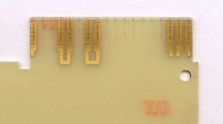
M9047 Grant Continuity Card
Enlarge
Connects AM2 to AN2 and AR2 to AS2