

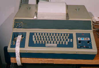
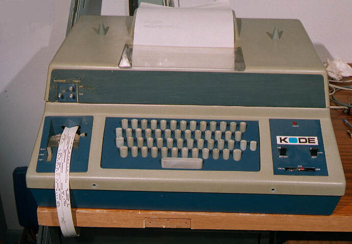
Teletype KODE ASR33
Inventory No: 0119
The teletype illustrated is not the classic teletype shape but has the same mechanism encased in a rather squalid plastic acoustic casing.
The type 33 teletype came in two variants; ASR (Automatic Send Receive) and KSR (Keyboard Send Receive). The ASR type has a built-in paper-tape reader and punch, the KSR is just a keyboard and printer.
The ASR33 was a widely used I/O device because as well as acting as a terminal, it could used to punch and read paper-tapes. The teletype communicated at 110 Baud, which worked out as 10 characters per second because the device needed two stop bits to separate the characters.
Teletype waveform for U
Inventory No: 0119
The teletype transmitted information serially as 7-bit ASCII codes with (usually) even parity.
TELL ME More about ASCII Parity & Teletypes
The waveform shown is for "U", whose ASCII value is 85 decimal or 01010101 binary. With even parity the 8th bit remains unchanged as a zero. This is transmitted as the pattern shown in the diagram.
When the teletype is receiving data, the start pulse is necessary to wake up the machine and start it running. It can then decode the next eight pulses. The two stop bits at the end provide a pause between characters give time for the machine to recover before starting on the next character.
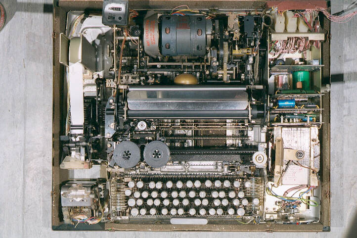
ASR 33 Teletype - cover removed
Inventory No: 0119
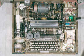
The teletype with its cover removed. On the far left from top to bottom: An almost used reel of paper tape, feeding into the punch. Then there is a small gap and the block at the bottom is the papertape reader. When operating, paper tape is fed to this reader from below.
In the central section from the top to the bottom: The drive motor, this runs continuously while the teletype is being used, but shuts down after a given period of inactivity. To the right of this is the clutch mechanism and the distributor assembly, (which is a mechanical parallel to serial converter).
The clutch mechanism controls the distributor and also the selector mechanism such that when a character is typed on the keyboard or one is received on the serial input line, then the clutch is released. When this happens, the mechanism makes one complete revolution and then locks again. Gerr-Klunk. (More about this later).
Next is the platen and in front of this the silver circle of the type wheel with its attendant ribbon spools. Just in front of the platen down in the depths of the machine can be seen a couple of the printer codebars (more about these later). At the very front of the teletype, at the bottom of the photograph is the keyboard.
On the right is the power supply and interface circuitry.
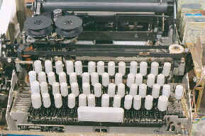
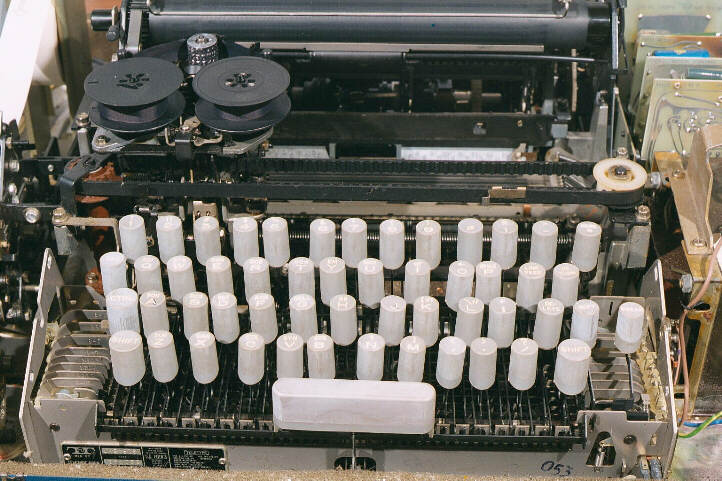
Teletype Kode ASR33 Opened - Detail
At the rear left, behind the ribbon spools, can be seen the cylindrical type wheel. At the front is the keyboard and at either side of this the (silver) ends of the coding bars can be seen.
The coding bars run under the keys from side to side. Each key is connected to a bar that runs front to back and rests across the coding bars. So, when a key is depressed it pushes down all the bars.
No it doesn't!
The coding bars are slotted in a cunning manner so that when a key is depressed, it only moves some bars. The bars move down according to the key's ascii value in an exact mechanical equivalent of an 8-bit bus. At the right of the keyboard a series of switches converts the movement of the code bars into electrical signals on a bundle of 8 wires, an 8 bit parallel bus (7 data plus 1 parity).
These 8 wires are connected to the distributor, a ring of contacts. A single moving arm sweeps over this ring, reading each contact in turn and sending its state off down the line as a serial stream of bits. In addition, the distributor adds a start bit at the beginning and a double length bit at the end to make 11 bits in total. If the teletype is on line, these 11 bits are transmitted down the line. If the teletype is in local mode, the 11 bits are sent to the selector mechanism and the character is printed locally.
Unfortunately, the print mechanism isn't quite so straightforward as the typing mechanism!
When a start pulse is received, the selector mechanism starts to turn. It will complete one revolution and then stop. Very cleverly, the mechanism is arranged so that the selector completes its single turn in the same time that it takes for all the eight data pulses to arrive.
On the selector mechanism are a series of eight nearly circular cams, each of which has a single indentation. These indentations are positioned in a staggered fashion, each corresponds to a data bit of the serial stream. Every "1" that is received activates an electromagnet, (zeros have no effect). The electromagnet and the cams control the movement of blocking levers according to the following rule:-
     IF the magnet is activated  (has a "1" been received?)
     AND the indentation is in the right place (is this "1" the right one?)
     THEN the blocking lever moves.
In this way, for instance, the third pulse to arrive controls the third lever (because that is when the indentation on the third cam is in the right place) and so on. The blocking levers that have been selected in this way lock the movement of the corresponding printer codebars so that they cannot move.
Towards the end of the cycle, the remaining free printer code bars are lifted and this raises and positions the type wheel, so that the correct character is facing the paper. The type wheel is then struck a cruel blow on the back of its head by the print hammer and nodding forward, types a character on the page.
This process is repeated at the rate of ten characters per second - it is very noisy - it is a miracle that it works.