

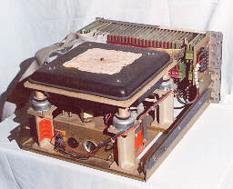
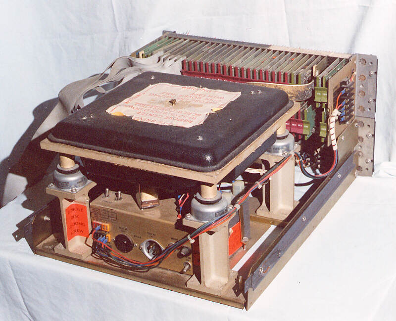
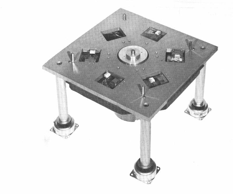
DF-32 Disk Drive - ¾ Rear View
Inventory No: 0190/002
The DF32 disk file system was originally intended for use with PDP-8, 8/I or 8/L computers. However, this one belongs to a PDP-8/f system. Each disk has a capacity of 32,768 13-bit words and four can be combined into a single subsystem, giving a total capacity of 131,072 words. Data are stored on a 10 inch diameter aluminium disk, which has a nickel-cobalt, rhodium plated surface.
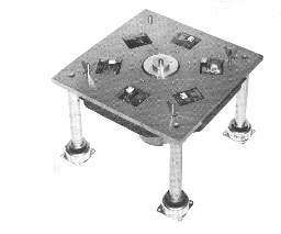
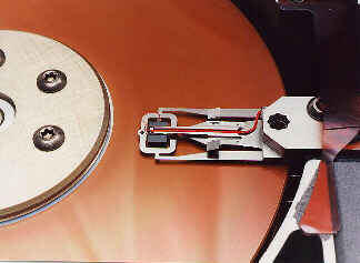
DEC DF32 Disk File - Recording Heads Exposed
This illustration is taken from the DF32 manual (Figure 1-3). The dust cover and the disk itself have been removed and the fixed heads which lie below the disk are visible. There are five head pads, each of which holds four heads. There are twenty tracks on the disk, 16 data, two timing and two spare for use if the timing tracks fail. Unlike a modern drive, the heads do not move onto a data track, but tracks are selected by switching the heads.
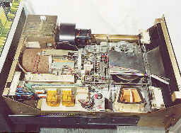
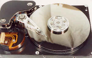
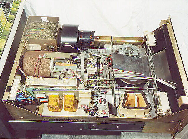
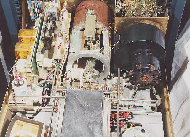
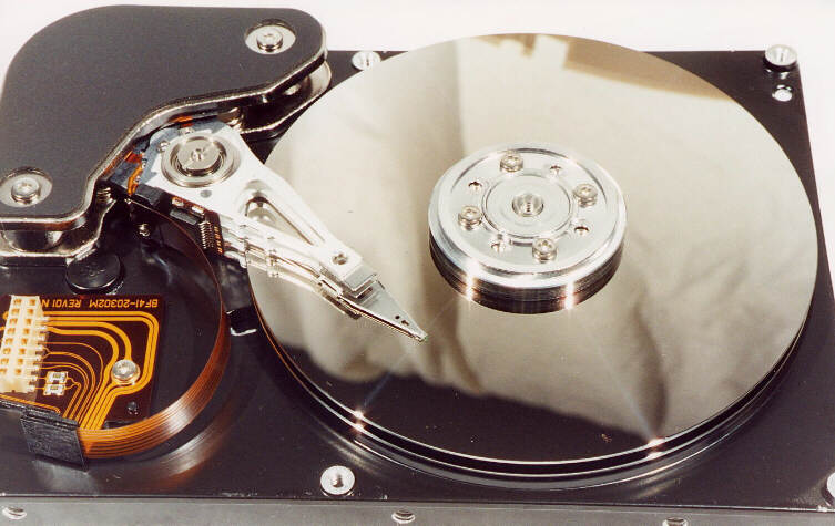
RK05 disk drive - disk not present.
Inventory No: 0001B
An RK05 disk drive with its cover removed. The removable disk is mounted in a plastic cartridge and fits into the wire rack visible on the right of the drive. The heads are positioned by the rust coloured drive unit, centre left of the illustration. Sadly, this drive has suffered in storage and the rust 'colouration' is genuine rust.
(Rust never sleeps).

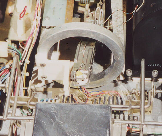
RK05 disk drive - heads
The heads are visible within the ring of the head positioning assembly. head detail (54703 bytes) As the heads are with drawn from the disk and retract into the ring, projections on the side of the heads make contact with the plastic bracket visible on the left of the ring and this forces the heads safely apart.
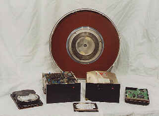
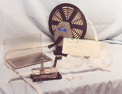
Assorted disks and drives.
This makes quite an effective test card for monitors. The disk at the rear of the picture is NOT egg shaped, I checked!.
The disk at the rear is from a 14 inch disk cartridge similar in appearance to an RL02 disk and similar in size to an RK05 disk. It has (had) a capacity of 10 MB. In the middle row from left to right there are a modern AT drive with a capacity of may be 4.3GB, next an ST412 10MB full height drive, showing the electronics, next an ST412 full height 10 MB drive the right way up and finally a modern AT drive inverted to show the PCB.
In the front row, a 4.3GB drive from a laptop. It would take 430 14 inch disks like the one in the back row to hold this amount of information. In the case of an RL02, the drive weighed 70lbs. So, comparing weights, the lap-top drive weighs about 3½ ounces and the same capacity using RL02 drives would weigh 70 × 430lbs, or roughly 13.4 tons.
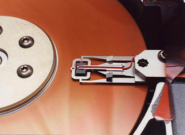
Head assembly of ST412 Drive.
The head assembly of a 10MB drive similar to ones fitted to Rainbow, DECmate II, PDP-11/23. Compare this to the RK05 heads illustrated above; although much smaller, the linear drive mechanism is similar.
Head assembly of an AT Drive.
The head assembly of a 4.3GB drive of the type fitted to newish PCs. (Hopefully, this should save you from having to take yours apart to see what is inside it).
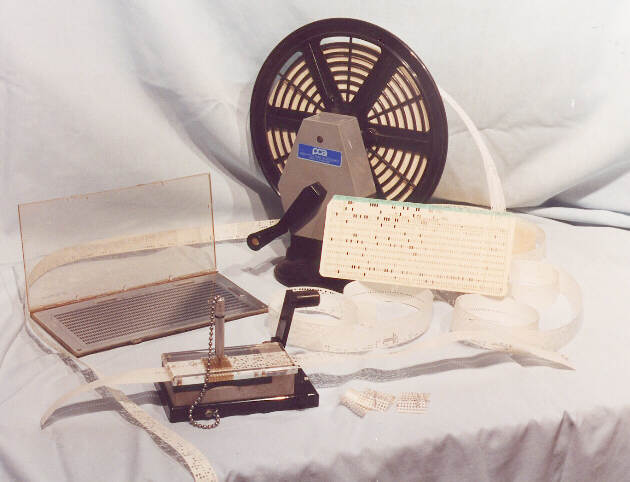
Punch Cards, tape and accessories.
An array of varied punch tape and card relics.
A Card punch alignment checker. The backplate of this was printed with the hole pattern and a card could be placed over this to check the alignment of the holes punched in it.
Paper tape winder and reel of tape. When paper tape was punched or read, especially at high speed, the tape was frequently fed on to the floor, or sometimes into a large container drum, like a dustbin. It then had to be rewound for reuse, hopefully without being torn.
A standard 80 column punched card.
A paper-tape editor and splicing jig. The paper tape was put into the jig and edited by punching individual holes with the stylus. The tape could also be cut, using the guillotine (the black handle on the right) and a new length joined on using the special sticky splices (seen just to the right of the jig).
Both eight hole and five hole paper tape are illustrated, but you need to look very closely to see the difference. A length of five hole tape runs on the left of the illustration from behind the card alignment checker. The loose coils in the centre and the tape in the editing jig are eight hole tape.