

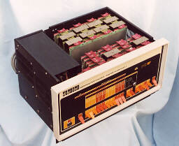
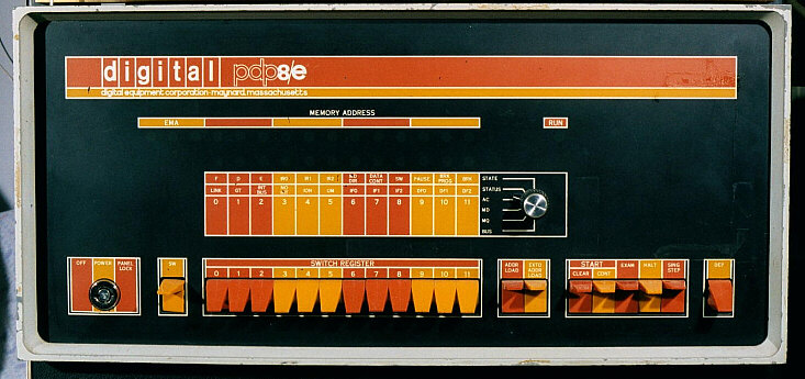
PDP-8/E Computer.
Inventory No: 0002
The PDP8/E was perhaps the most successful of the series. It introduced the OMNIBUS backplane in which equivalent positions in each slot were connected identically via a printed circuit. This was a more flexible design and much cheaper to implement.
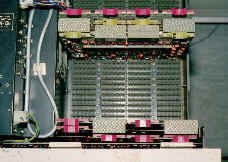
PDP-8/E Processor - Memory and Omnibus Backplane
Looking vertically down onto the OMNIBUS. This is superficially similar to the PDP-8 backplane but each slot has double sided connectors. The bezel of the front panel is visible at the bottom of the photograph and the power supply is on the left.
The OMNIBUS backplane of the PDP-8/e consists of 2 separate blocks. Each could hold 20 boards, (although to jumper the boards together took 1 slot from each). In the photograph, only the front one is visible; the other, in fact, is not connected. All modules have been removed except the processor (the front three modules, M8330, M8310, M8300), the 4KW memory (G104, H220, G227) and bus terminator at the rear, M8320.
Slot 1 of the omnibus is always occupied by the programmer's console. This is just visible in the photograph, immediately behind the front panel. This holds the switches, lights and associated control circuitry for the console. It is not possible to remove this module without dismantling the front panel.
The rectangular blocks visible on top of the boards (2 on the CPU and 4 on the memory) are H851 inter-board connectors, connecting adjacent pairs of boards.
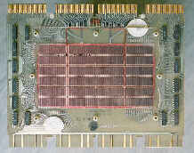
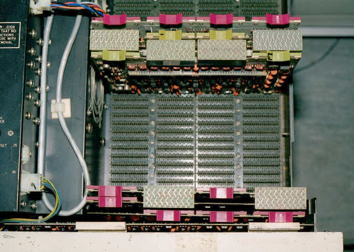
PDP-8/E Core Memory (4K words).
The 4K core memory stack. In the centre, under a protective perspex screen, are 49,152 ferrite rings (12 × 4096) and each one has three wires threaded through it. The bundles of wires can be seen as the pinkish strands round the edge of the core.
The H220 module has connectors at the top and bottom of the board. Those at the top are for the inter-board jumpers to connect to the adjacent support modules, G104 and G227. Together, these three boards provide 4K 12-bit words of memory.
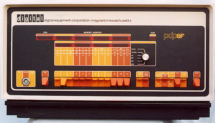
PDP-8/F Computer.
Inventory No: 0190
The PDP-8/F is a later and slightly reduced version of the PDP-8/E. The 8/F has a smaller and lighter switched mode power supply than the linear power supply of the 8/E. The OMNIBUS backplane of the 8/F is half the size of the 8/E's backplane, )10 slots as opposed to 20). The only other difference between the two machines is that the 8/F uses LED lamps rather than filament bulbs in the programmer's console.
PDP-8/F - Power Supply, Memory and Omnibus.
Looking down onto the opened computer. The smaller power supply can be seen to the left of the backplane. As with the PDP-8/E described above, the programmer's console occupies the first OMNIBUS slot. This is followed by M8330 (Timing Generator), M8310 (Major Register Control), M8300 (Major Registers). Slot 5 holds M837 (Memory Extension and Timeshare), this is necessary if more than one plane (4K) of core is fitted. Next comes M848 (Power fail and Auto Restart).
Two planes of core memory are present (8K words).