

The PDP-8/A is the final refinement of the bus based PDP-8s. The CPU (the KK8-A) now only requires one hex-high board. The omnibus is mounted vertically at the back of the case and circuit boards plug in horizontally.
There are two types of 8/A, depending on the type of memory fitted. The basic model was supplied with semiconductor memory, which was available in 1,2 or 4K word modules. This had a standard quad omnibus, like the PDP-8/e, but with only 10 slots.
The second type of PDP-8/A was fitted with core memory. Core memory was supplied in 8 or 16 K word modules. This required a 5 high omnibus.
The situation is complicated by the fact that some models of
PDP-8/A were originally fitted with the PDP-8/e CPU (which is
faster). The basic models are:-
| Computer | CPU | Memory | Omnibus | Floating Point FPP-8/A? |
Expandable? |
|---|---|---|---|---|---|
| PDP-8/A | KK8-a | Semiconductor | 10 Slots | No | No |
| 8A400 | KK8-A | Core | 12 Slots | No | No |
| 8A420 | KK8-A | Core | 20 Slots | No | No |
| 8A600 | KK8-E | Core | 12 Slots | No | Yes, add up to 20 more slots |
| 8A620 | KK8-E | Core | 20 Slots | No | Yes, add up to 20 more slots |
| 8A800 | KK8-A | Core | 12 Slots | Yes | No |
| 8A820 | KK8-A | Core | 20 Slots | Yes | No |
The 800 and 820 models were fitted with the floating point option, FPP-8/A. In all other respects, they are identical to models 400 and 420.
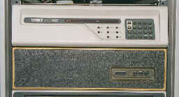
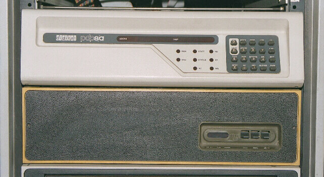
PDP-8/A 400 Computer.
Inventory No: 0093
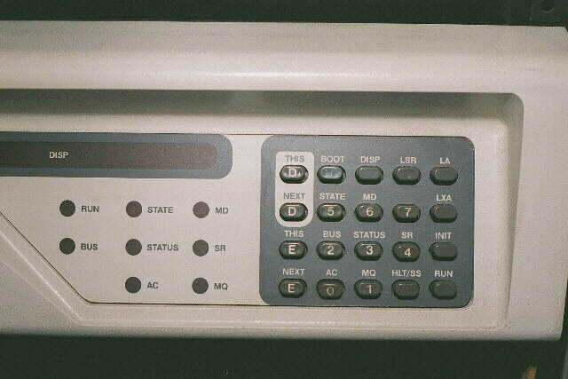
The PDP-8/A console has been reduced to a keypad and 7 segment LED display. Keypad - detail (33776 bytes) By the time the PDP-8/A was produced it was possible to store bootstrap routines in ROM and the PDP-8/A has built-in routines for booting off several different peripherals. The programmer's console was no longer needed if these routines were used and so some machines were sold with the basic console only. This has a switch to start the boot process.
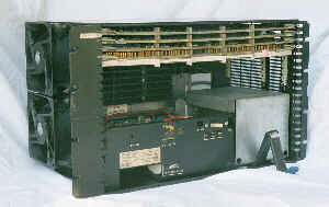
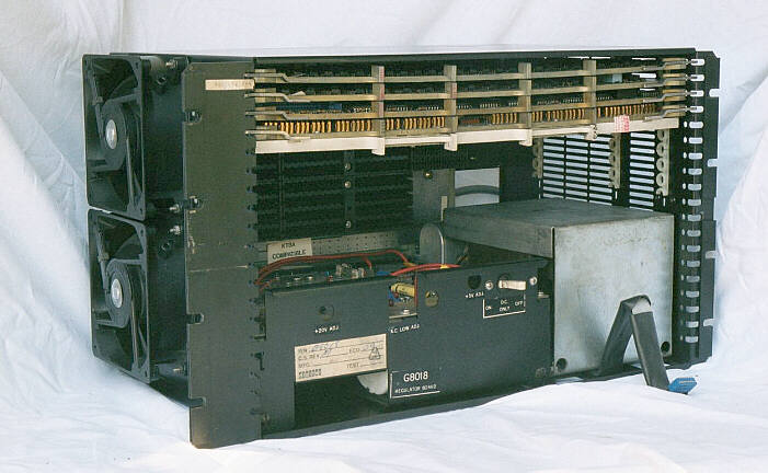
PDP-8/A 400 Inside the case.
With the console panels removed, we can see across the top of the case, the CPU board, option boards 1 & 2 and Core memory on the two siamesed boards at the bottom of the stack.
At lower left is the G8018 power supply and on the right the transformer for operation on UK voltages. Below this, the ribbon cable to connect to the basic console panel.
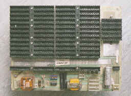
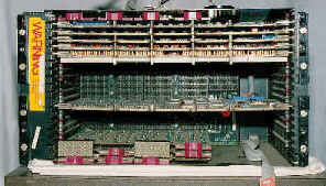
PDP-8/A 400 The Backplane.
The backplane, removed from its case. The omnibus is largely formed in one block and has an additional block of connectors tacked on to the side. Slots 1-3, which take the CPU and option boards 1 & 2 are quad, as are slots 9 to 12. Slots 4 to 8 have 5 sets of connectors and are for core memory. There does not seen to be an accepted term for these.
The isolated line of omnibus at the bottom is where the G8018 power supply PCB plugs in.
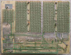
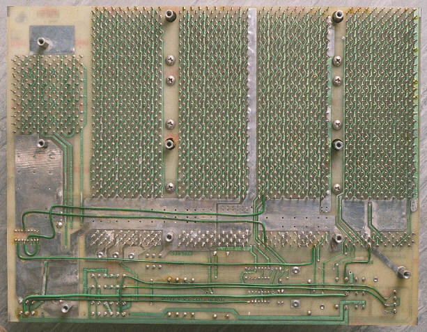
PDP-8/A 400 The Backplane Wiring.
The rear of the 8/a 400 omnibus. The four slot omnibus section of the illustration shows the rippling pattern of the printed circuit which interconnects the equivalent positions in each slot. Compare this with the wire wrapped backplane of the original PDP-8 and see why the omnibus implementation was so cost effective.
The fifth slot is on the upper left of the image and the power-supply wiring at the bottom.
(The PDP-8/e omnibus wiring is identical to the four slot omnibus section of this illustration).
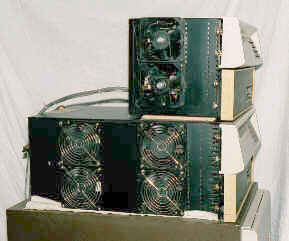
PDP-8/A 620 Computer.
Inventory No: 0102
From the front, the PDP-8/A 620 looks identical to the 400 model (seen above), but from the side their differences are obvious. The 620 has a much deeper case. The reason for this is that boards fitting into the 20 slot omnibus take up all of the front of the unit and the power supplies (now 2 to accommodate increased requirements) are housed at the back of the case.
PDP-8/A 620 Inside the case.
Looking into the case of the 620. The first thing to notice is the presence of quad boards with MAGENTA handles! This machine is fitted with an 8/E CPU.
The CPU is fitted at the bottom of the case and the bus terminator is fitted at the very top.
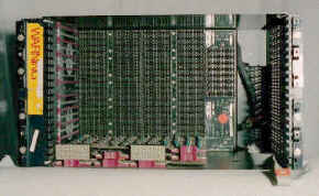
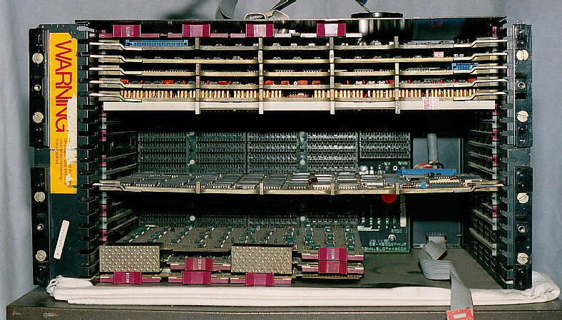
PDP-8/A 620 The Backplane.
The 620 with most of its boards removed. Only the 8/E CPU remains at the bottom. Again, it can be seen that the omnibus is largely quad, but there is provision for core memory at positions 4 to 11.
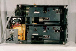
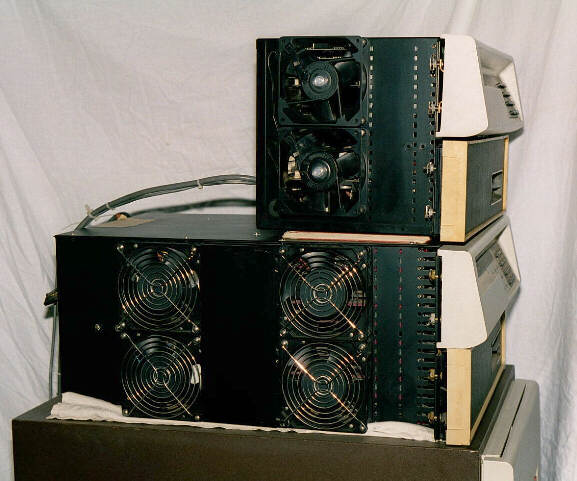
PDP-8/A 620 The Rear of the Cabinet.
The rear of the cabinet, with the two power supplies mounted one over the other.